Saturday, December 5, 2009

AC Line Current Detector Circuit

AC Line Current Detector
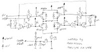
This circuit will detect AC line currents of about 250 mA or more without making any electrical connections to the line. Current is detected by passing one of the AC lines through an inductive pickup (L1) made with a 1 inch diameter U-bolt wound with 800 turns of #30 - #35 magnet wire. The pickup could be made from other iron type rings or transformer cores that allows enough space to pass one of the AC lines through the center. Only one of the current carrying lines, either the line or the neutral should be put through the center of the pickup to avoid the fields cancelling. I tested the circuit using a 2 wire extension cord which I had separated the twin wires a small distance with an exacto knife to allow the U-bolt to encircle only one wire.


more


A Unique Discrete Zero-Crossing Detector
A zero-crossing detector delivers an output pulse that synchronizes other circuitry to the transitions through zero volts of a sinusodial source for both polarity excursions. This detector, which was developed to operate from the ac power line, includes a unique negative-voltage detector/level shifter


more

AC Line Sensing – Zero-Crossing Detector


The circuit I came up with is very inexpensive and works as follows. The AC line goes through some resistors to limit the current. The resistors are shown as two parts in parallel, but this is just to split the power between them since they may get a bit warm. The AC voltage goes into a bridge rectifier.

more


AC Current Indicator Light Circuit

This circuit could be wired into a 120vac power line, which feeds power to any load, ranging from 40 watts to 250 watts. It will turn on a LED light whenever current is being drawn by a load. It is especially useful for remote lights, where you may not be able to see if the lamps are receiving power.

more

Method and system for line current detection for power line cords

spects for detecting current flow in a power line cord are described. In these aspects, a line current detector circuit is provided for each input plug line of a power distribution box. A determination of whether line current is flowing in a system line cord plugged into the power distribution box is based on a light indicator from the line detector circuit. The line current detector circuit includes a magnetic device for detecting line current flowing in a power line cord, and a light emitting diode (LED) coupled to the magnetic device for outputting a light indicative of whether current is flowing in the power line cord.


more

Friday, November 13, 2009

Isolation Triac Driver Circuit

Isolation Triac Driver Circuit - Resistive Load


Isolation Triac Driver Circuit - Inductive Load with Sensitive Gate Triac (IGT ≤15 mA)


Isolation Triac Driver Circuit - the “hot” side of the line is switched and the load connected to the cold or ground side.


OPTOISOLATORS TRIAC DRIVER OUTPUT
DESCRIPTION
The MOC301XM and MOC302XM series are optically
isolated triac driver devices. These devices contain a
AlGaAs infrared emitting diode and a light activated silicon
bilateral switch, which functions like a triac. They
are designed for interfacing between electronic controls
and power triacs to control resistive and inductive loads
for 115/240 VAC operations.

FEATURES
• Excellent IFT stability IR emitting diode has low degradation
• High isolation voltage minimum 5300 VAC RMS
• Underwriters Laboratory (UL) recognizedFile #E90700
• Peak blocking voltage
-250V-MOC301XM
-400V-MOC302XM
• VDE recognized
-Ordering option V

Tuesday, July 28, 2009

SD/MMC Card interfacing with Microcontroller Circuit Project

SD/MMC Card interfacing with MUC with AVR Microcontrollers
Interfacing with ATMega 162:

It is easy to interface a MMC (Multimedia Card) with an Atmel ATmega162 (AVR series) via the SPI (Serial Port Interface). The MMC is connected to the SPI pins of the ATmega16 via simple resistor voltage dividers to transform the +5V high levels to about 3.3V used by the MMC. If the Atmega-162 is working on 3.3 V power supply then all the MMC pins can be directly connected to Microcontroller (as in this design). The data-out pin from the MMC goes directly to the ATmega162, because 3.3V is high for the ATmega162 anyway. The schematic of the MMC interfacing is given below.


http://devusb.googlepages.com/sdmmcinterfacing

Microcontroller board with Ethernet, MMC/SD card interface and USB
Hardware components already integrated on the reference design include:
• Atmel ATmega128 RISC microcontroller with standard 10-pin ISP header
• 64 kByte of external SRAM
• USB <-> RS232 interface
• SD/MMC socket
• Ethernet interface with ENC28J60 (IEEE 802.3, 10Base-T)
The hardware design is expandable by connecting additional components to the existing pin header. Several digitial I/Os, A/D inputs as well as the standard SPI and I2C (TWI) serial interfaces are available for user-defined purposes.
The curcuit board is designed as a two-layer board of size 100mm x 80mm. Most components use SMD packages.


http://www.roland-riegel.de/mega-eth/index.html

SD/MMC Interface Integration Guidelines
SD/MMC cards provide a low cost solution for data logging and storage applications
for embedded systems. SD/MMC cards can be easily interfaced with a
Microcontroller using an SPI interface and between one and three control lines. While
the electrical interface is relatively straight forward, successfully implementing a
solution can be time consuming for the initial implementation. This document looks at
some of the common pitfalls encountered. The document assumes the developer is
implementing Brush Electronics SD/MMC File System drivers or Utilities with a
Microchip PIC Microcontroller however the principles apply to other implementations.

http://www.smallridge.com.au/download/SD-MMC%20Integration.pdf


MMC/SD Card interfacing and FAT16 Filesystem with 8051/8052

Content

# Interface to Chan’s Library of functions

# Target development platform

# Setting up the SPI port during startup.A51

# Global type definitions and variables

# Basic SPI function

1. Transferring & Receiving single byte over SPI Bus
2. SPI Chip Select
3. Setting frequency for SPI Clock
4. Sending command to SD Card
5. Reading response from SD Card
6. Delay and Time function

# SD Card Initialization

1. Setting up the card for SPI Communication

# Reading and Writing a single sector

# Working with diskio.c

# Pulling it all together

http://www.8051projects.net/mmc-sd-interface-fat16/MMC-SD-Card-interfacing-and-FAT16-Filesystem.pdf

Saturday, July 18, 2009

H-Bridge Motor Driver Circuit

H-Bridge
This circuit drives small DC motors up to about 100 watts or 5 amps or 40 volts, whichever comes first. Using bigger parts could make it more powerful. Using a real H-bridge IC makes sense for this size of motor, but hobbyists love to do it themselves, and I thought it was about time to show a tested H-bridge motor driver that didn't use exotic parts.


http://www.bobblick.com/techref/projects/hbridge/hbridge.html

H-bridge using P and N channel FETs
This H-bridge uses MOSFETs for one main reason - to improve the efficiency of the bridge. When BJT transistors (normal transistors) were used, they had a saturation voltage of approximately 1V across the collector emitter junction when turned on. My power supply was 10V and I was consuming 2V across the two transistor required to control the direction of the motor. 20% of my power was eaten up by the transistors. I tried darlingtons etc... nothing worked. The transistors also would get quite hot - no room for heatsinks.


http://www.armory.com/~rstevew/Public/Motors/H-Bridges/Blanchard/h-bridge.htm


N-Channel H-bridge Motor Drive
In low voltage motor drives, it is common practice to use
complementary MOSFET half-bridges to simplify the gate
drive design. However, the P-channel FET within the
half-bridge usually has a higher on resistance or is larger
and more expensive than the N-channel FET. The alternative
solution is to design in an N-channel half-bridge.


http://www.eetkorea.com/ARTICLES/2004MAY/2004MAY18_BD_MSD_PD_AN.PDF

Comparator Controlled H-Bridge Circuits (LM311)
The next two circuits are simple Bi-Polar H-Bridge circuits. The bridges are controlled by a pair of LM311 voltage Comparators.
The LM311 Voltage Comparator has several unique features, one of which is an output transistor with an open emitter as well as the typical open collector. This allows the output transistor of the comparator to sit between the bases of the power transistors.


http://home.cogeco.ca/~rpaisley4/HBridge.html

Robot Motor control
In order to control the speed/torque of a motor, a so called H-bridge can be used. I built/designed one myself, using 4 MOSFETs.


http://www.iwhat.nl/rienatmarobi/bots/Wheeley/motor/index.html

Bidirectional operation (H-bridge circuit)
We have achieved speed control and have made a powerful drive circuit. However in robotic work we also usually want to be able to drive a motor either clockwise or counterclockwise. Before we discuss the use of transistors to solve this problem


http://www.mech.uwa.edu.au/NWS/How_to_do_stuff/micro_crash_course/pwm/

Saturday, July 11, 2009

DC Motor Speed Control Circuit

Speed Controller Circuit
The robot I intend to build will be a 4WD bot with a skid steer system so to do this best I have opted to build 2 a controller system moulded around a 4QD DCI111. (A DCI111 converts radio signals into useable signals) Because of this the inputs on my controllers have to be similar to the 4QD units. The next things to consider are the motors that I will be using. Bosch 750’s seem to be quite popular (so are ford escorts and they are crap) so I will just go ahed and use the many starter motors that I have lying around. This results in


more

DC Motor Control & Interfacing Circuit
A permanent magnet DC motor responds to both voltage and current. The steady state voltage across a motor determines the motor’s running speed, and the current through its armature windings determines the torque. Apply a voltage and the motor will start running in one direction; reverse the polarity and the direction will be reversed. If you apply a load to the motor shaft, it will draw more current, if the power supply does not able to provide enough current, the voltage will drop and the speed of the motor will be reduced. However, if the power supply can maintain voltage while supplying the current, the motor will run at the same speed. In general, you can control the speed by applying the appropriate voltage, while torque is controlled by current. In most cases, DC motors are powered up by using fixed DC power supply, therefore; it is more efficient to use a chopping circuit.


more


PWM D.C. motor drive Circuit
This circuit is a very compact switching regulator for small DC motors. I use it for my small printed circuit board drill (18 Volt, 1.5 Amp), but it is suitable for many other applications (e.g. 12V DC halogen dimmer).


more

Back EMF PM Motor Speed Control Circuit


A 12 V control supply and a TRW BL11, 30 V motor are used; with minor changes other motor and control voltages can be accommodated. For example, a single 24 V rail could supply both control and motor voltages. Motor and control voltages are kept separate here because CMOS logic is used to start, stop, reverse and oscillate the motor with a variable delay between motor reversals.
more


Bidirectional DC Motor Speed Controller
This kit allows controlling the speed of a DC motor in
both the forward and reverse direction. The range of
control is from fully OFF to fully ON in both directions.

This kit overcomes both these problems. The direction and
speed is controlled using a single potentiometer. Turning
the pot in one direction causes the motor to start spinning.
Turning the pot in the other direction causes the motor to
spin in the opposite direction. The center position on the
pot is OFF, forcing the motor to slow and stop before
changing direction.


more pdf

PWM DC Motor Speed Control


The left half of the 556 dual timer IC is used as a fixed frequency square wave oscillator. The oscillator signal is fed into the right half of the 556 which is configured as a variable pulse width one-shot monostable multivibrator (pulse stretcher).
more

DC Motor Controlled with PWM Resources
Here is a description of the driver circuit. It's based on the Microchip AN531 Application Note titled "Remote Positionner". The circuit given in the application Note do not work , so this is a correction of the circuit:


more

DC MOTOR CONTROL USING A SINGLE SWITCH
This simple circuit lets you run a DC motor in clockwise or anti-clockwise
direction and stop it using a single switch. It provides a constant voltage for
proper operation of the motor. The glowing of LED1 through LED3 indicates that
the motor is in stop, forward rotation and reverse conditions, respectively.


more pdf


Bidirectional DC motor speed control using Pulse Width Modulation
The simplest method of implementing microcontroller controlled H-bridge drive of a reversible DC motor is to buy one of many commercial H-bridge IC's availible on the market. These can be purchased separately as an H-Bridge with a separate H-Bridge controller IC, or as an all-in-one IC. Unfortunately, there are several hurdles that sometimes frustrate this approach. Students often find these devices hard to find, as they are apparently in high demand. Secondly, many of these devices have limited current drive ability, such that larger DC motors end up running sluggish or stalling easily. One option is to build your own H-bridge from discrete parts, as shown below.


more

Low-Cost DC Motor Speed Control with CMOS ICs
Two low-cost CMOS ICs manage a 12 VDC, current-limited speed
control circuit for DC brush motors. The circuit design (see
Figure 1) uses PWM (pulse width modulation) to chop the effective
input voltage to the motor. Use of CMOS devices gives the benefits
of low power, minimal heat and improved longevity. The overall
design is simple, inexpensive and reliable, and is useful in applications
such as embedded DC motor control where efficiency,
economy and performance are essential.


more pdf

Digital Speed Control by Anthony Psaila
My design is based around three parts:
1. The controller board. This is a fully digital circuit that takes the 1ms to 2ms pulse from the receiver and converts it into a pwm train at 1Khz. It uses six cmos ics (74hc and 40 series) and a 4Mhz crystal clock. The only other components are one resistor and two capacitors to complete the crystal clock and a capacitor across the supply for smoothing. This was built on a printed board measuring 2 x 2.25 inches using standard components (on the boat there was no shortage of space). If surface mounted devices are used, the lot can be crammed into a much smaller space. The circuit can give a resolution of 128 steps (7bits). Some day I will expand it to have reverse function, but this is better done by a switcher circuit supplied from another channel (my reciever can give 7 channels and I am using only two at present).


more

Friday, July 3, 2009

Brushless DC Motors Theory and Driver Circuit


Why use brushless DC motors (advantages/disadvantages)?
Brushless DC motors are synchronous motors suitable for use as a simple means of controlling permanent drives (e.g. ABS pumps, EHPS pumps, fuel pumps or cooling fans). This type of 3-, 4- or 5-phase brushless DC motor will increasingly replace brushed DC motors. Brushed DC motors require maintenance, e.g. to service coal brushes and commutator. Another major problem with a brushed DC machine is the possibility of brush burnout in the event of an overload or stall condition.

Functional principle of a brushless DC motor
Figure 1 shows a three-phase brushless DC motor with two pole pairs. The rotation of the electrical field (vector) has to be applied twice as fast as the desired mechanical speed of the brushless DC motor. The three coils of the stator are split into two groups of coils (A, B, C and A’, B’, C’). As you can see in Figure 1, coils A and C are energized and coil B is not energized. A 0° to 180° rotation will be shown in detail in section 2.1 to explain the setting of the appropriate switches of the B6 bridge pattern, the appropriate voltages relating to the coils, and the energized coils of the motor with the suitable rotor position between 0° and 180° mechanical.


Brushless DC Motors wiring diagrams
The wiring diagrams for a 3-pole armature (stator) Brushless DC Motors


The wiring diagrams for a 6-pole armature Brushless DC Motors


more

Brushless DC Motors Animation
Brushless DC motors are refered to by many aliases: brushless permanent magnet, permanent magnet ac motors, permanent magnet synchronous motors ect. The confusion arises because a brushless dc motor does not directly operate off a dc voltage source. However, as we shall see, the basic principle of operation is similar to a dc motor.


more

Introduction to Brushless DC Motors
Brushless Motor Construction
DC brushless motors are similar in performance and application to brush-type DC motors. Both have a speed vs. torque curve which is linear or nearly linear. The motors differ, however, in construction and method of commutation. A brush-type permanent magnet DC motor usually consists of an outer permanent magnet field and an inner rotating armature. A mechanical arrangement of commutator bars and brushes switches the current in the armature windings to maintain rotation. A DC brushless motor has a wound stator, a permanent magnet rotor assembly, and internal or external devices to sense rotor position. The sensing devices provide signals for electronically switching (commutating) the stator windings in the proper sequence to maintain rotation of the magnet assembly. The rotor assembly may be internal or external to the stator in a DC brushless motor. The combination of an inner permanent magnet rotor and outer windings offers the advantages of lower rotor inertia and more efficient heat dissipation than DC brush-type construction. The elimination of brushes reduces maintenance, increases life and reliability, and reduces noise and EMI generation.
DC Brushless Motor Control Block Diagram


more


Brushless DC Motor driver circuit

Closed Loop Brushless DC Motor Control With the MC33033 Using the MC33039 driver circuit

The MC33033 is a high performance second generation, limited
feature, monolithic brushless dc motor controller which has evolved
from ON Semiconductor's full featured MC33034 and MC33035
controllers. It contains all of the active functions required for the
implementation of open loop, three or four phase motor control. The
device consists of a rotor position decoder for proper commutation
sequencing, temperature compensated reference capable of supplying
sensor power, frequency programmable sawtooth oscillator, fully
accessible error amplifier, pulse width modulator comparator, three
open collector top drivers, and three high current totem pole bottom
drivers ideally suited for driving power MOSFETs. Unlike its
predecessors, it does not feature separate drive circuit supply and
ground pins, brake input, or fault output signal.


more pdf

THREE-PHASE BRUSHLESS DC MOTOR driver circuit

The L6235 is a DMOS Fully Integrated Three-Phase
Motor Driver with Overcurrent Protection.
Realized in MultiPower-BCD technology, the device
combines isolated DMOS Power Transistors with
CMOS and bipolar circuits on the same chip.
The device includes all the circuitry needed to drive a
three-phase BLDC motor including: a three-phase
DMOS Bridge, a constant off time PWM Current Controller
and the decoding logic for single ended hall
sensors that generates the required sequence for the
power stage.


more pdf

3-Phase Full-Wave PWM Driver for Sensorless brushless Motors driver circuit
The TB6588FG is a three-phase full-wave PWM driver for
sensorless brushless DC (BLDC) motors. It controls rotation speed
by changing the PWM duty cycle, based on the voltage of an
analog control input.

more pdf

Saturday, June 20, 2009

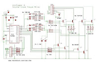
Microstepping Stepper Motor Driver Project

Microstepping Stepper Motor Data


Microstepping of Stepping Motors
Introduction
Microstepping serves two purposes. First, it allows a stepping motor to stop and hold a position between the full or half-step positions, second, it largely eliminates the jerky character of low speed stepping motor operation and the noise at intermediate speeds, and third, it reduces problems with resonance.
Although some microstepping controllers offer hundreds of intermediate positions between steps, it is worth noting that microstepping does not generally offer great precision, both because of linearity problems and because of the effects of static friction.
1 Sine-Cosine Microstepping
2 Limits of Microstepping
- Detent Effects
- Quantization
3 Typical Control Circuits
- Practical Examples

http://www.cs.uiowa.edu/~jones/step/micro.html


Microstepping Stepper Motor Driver Kit

Basic design
It is a unipolar (or 5-wire type) driver. The motor must have
5 or 6 wires (or 8), as 4-wire motors are only for bipolar
and 4-WIRE MOTORS WILL NOT WORK WITH THIS BOARD.

The constant current system is crude but simple, it relies on
setting the base of the main transistors at a "set" level, then
this causes a "set" voltage across the sense resistor Rs, ie
maintains constant current. It does get some temp drift with
large currents, but it's simple and accurate enough with the
resistor values i've tested. It actually works quite well!

The brain has control of which of the 4 transistors are ON,
and sets 3 possible current levels, enough to do 6th stepping
and give 1200 steps/rev with hardware alone. The software I
have provided also will do pwm and give 18th stepping, which
is 3600 steps/rev, almost stepless operation.

The PIC has plenty of left over rom if you need to do motion
control or use the board as the complete brains and driver for
an entire machine. Up to 9 PIC in/out pins can be allocated to
the board.

http://www.piclist.com/tecHREF/io/stepper/linistep/lini_wks.htm


Micro-step driver

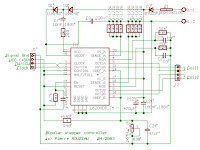
This circuit allows to connect a bipolar step motor to a personal computer through the parallel port. The circuit is, for safety reasons, optically isolated from the PC and it allows to manage motors up to 3A for phase. Moreover the digital interface allows to connect up to six motors to a single PC parallel port.
The more interesting aspect of this circuit is its ability to implement the microstep technique and to multiply up to 64 times the motor real steps number. As an example, a 200 steps motor could behave like "a virtual" 12.800 steps motor. This function is particularly useful when the spin speed is very low, in the order of fractions of rpm.


http://www.vincenzov.net/eng/design/microstep.htm


L6208 FULLY INTEGRATED TWO PHASE STEPPER MOTOR DRIVER

Modern motion control applications need more flexibility that can be addressed only with specialized IC products. The L6208 is a fully integrated stepper motor driver IC specifically developed to drive a wide range
of two phase (bipolar) stepper motors. This IC is a one-chip cost effective solution that includes several unique circuit design features. These features, including a decoding logic that can generate three different stepping sequences, allow the device to be used in many applications including microstepping. The principal aim of this development project was to produce an easy to use, fully protected power IC. In addition several key functions such as protection circuit and PWM current control drastically reduce external components count to meet requirements for many different applications.


Microstepping Stepper Motor Driver Circuit


http://www.st.com/stonline/books/pdf/docs/8607.pdf


MICROSTEPPING STEPPER MOTOR DRIVE
USING PEAK DETECTING CURRENT CONTROL

Stepper motors are very well suited for positioning applications since they can achieve very good positional accuracy without complicated feedback loops associated with servo systems. However their resolution, when driven in the conventional full or half step modes of operation, is limited by the configuration of the motor. Many designers today are seeking alternatives to increase the resolution of the stepper motor drives. This application note will
discuss implementation of microstepping drives using peak detecting current control where the sense resistor is connected between the bottom of the bridge and ground. Examples show the implementation of microstepping drives with several currently available chips and chip sets.

INTRODUCTION
Microstepping a stepper motor may be used to achieve one or both of two objectives; 1) increase the position resolution or 2) achieve smoother operation of the motor. In either case the basic theory of operation is the same. The simplified model of a stepper motor is a permanent magnet rotor and two coils on the stator separated by 90 degrees, as shown in Figure 1. In classical full step operation an equal current is delivered to each of the coils and the rotor will align itself with the resulting magnetic vector along one of the 45 degree axis. To step the motor, the current in one of the two coils is reversed and the rotor will rotate 90 degrees. The complete full step sequence is shown in figure 2. Half step drive, where the current in the coil is turned off for one step period before being turned on in the opposite direction, has been used to double the step resolution of a motor. In either full and half step drive,
the motor can be positioned only at one of the 4 (8 for half step) defined positions.[4][5] Therefore,
the number of steps per electrical revolution and the number of poles on the motor determine the resolution of the motor. Typical motors are designed for 1.8 degree steps (200 steps per revolution) or 7.5 degree steps (48 steps per revolution). The resolution may be doubled to 0.9 or 3.75 degrees by driving the motor in half step. Further increasing the resolution requires positioning the rotor at positions between the full step and half step positions.

Example alignment of microsteping

http://www.st.com/stonline/books/pdf/docs/8700.pdf

Precision Microstepping Driver Circuit


Microstepping Stepper Motor Driver Project

Functional description
The circuit can be divided into three functional blocks, Microprocessor simulation logic, micro-stepping controller and stepper motor driver.
A. Micro-stepping simulation.
This block send the control signals normally sent by a microprocessor to the micro-stepping controller, the inputs to the block are the 5 Dip-switches and the clock pulse from pin1 of J2. During normal operation the current level in one of the motor windings is updates at every step pulse (single pulse programming). These mean two step pulses are required to update both winding currents and make the motor turn. Operating the dip-switched S1-6 can change the direction of the motor rotation


http://home.att.net/~wzmicro/3960drv.html

Wednesday, June 10, 2009

Stepper Motor Driver Project

Unipolar Stepper Motor Driver Circuit
This project presents a circuit for driving high-power unipolar stepper motors. Here you will find all the information needed to make your own. This circuit allows step-level control and can be easily modified for other modes of operation

Circuit Schematic and Photo

The L297 has several inputs that can be generated by a PC/104 stack or other controller. This circuit allows you to control each step, in full-step mode. Meaning: You can tell it to move one step in either direction (of course you can make it move fast and it will continuously rotate). The two inputs are a direction and a pulse. In the next section you will find a program to control this using xPC.


http://hades.mech.northwestern.edu/wiki/index.php/Unipolar_Stepper_Motor_Driver_Circuit


Stepper motor driver circuit
Stepper Motor Data
Stepper Motor Data 1
Stepper Motor Data 2
Stepper Motor Data 3
Microstepping Data
Stepper Motor Driver Circuit
2A Step Motor Driver Circuit
bipolar stepper motor with current control
Microstep Stepper motor driver circuit
Precision Microstepping Driver Circuit
High Current Microstep Stepper Motor Driver
http://basicelectronic.blogspot.com/2009/02/stepper-motor-driver-circuit.html

Stepper motor control board
This project is actually an educational kit. One can study the full operation of unipolar type stepper motor using this board. As it is micro controller based it can be programmable also and one can learn micro controller interfacing with LEDs, key board and stepper motor. Thus single board serves the purpose of learning stepper motor control as well as learning micro controller programming.

In the construction of unipolar stepper motor there are four coils. One end of each coil is tide together and it gives common terminal which is always connected with positive terminal of supply. The other ends of each coil are given for interface. Specific color code may also be given. Like in my motor orange is first coil (L1), brown is second (L2), yellow is third (L3), black is fourth (L4) and red for common terminal.


http://electrofriends.com/microcontrollers/stepper-motor-control-board/

Stepper motor controller
The stepper motor driver circuit shown as following


The opto-isolator are important which prevent destroy of MCU by the feeback voltage from
power transistor. Two adjust-able voltage regulator used to adjust the running voltage and
stopping/holding voltage of the stepper motor.

http://www.geocities.com/mindtan2000/PIC.html


Remote Unipolar Stepper Motor Controller with 89C51
Abstract:- This is the third and most amazing application of multichannel IR remote where 4 different channels of remote are utilized to control all the parameters of unipolar stepper motor. All three parameters of stepper motor RPM, direction & no. of revolutions can be changed from remote. 89C51 takes care of all the controlling actions.

The project is based on stepper motor control and I have experimented with unipolar stepper motor. One must know first how this stepper motor is controlled. How it can be rotated, how RPM, direction & no. of revolutions can be changed etc. So let us first go through the theory of unipolar stepper motor


http://www.jasonbabcock.com/computing/breadboard/bipolar/index.html

Controlling Stepper Motor with a Parallel Port
This is an easy to build stepper motor driver that will allow you to precisely control a unipolar stepper motor through your computer's parallel port. With a stepper motor you can build a lot of interesting gadgets such as robots, elevator, PCB drilling mill, camera panning system, automatic fish feeder, etc. If you have never worked with stepper motors before you will surely have a lot of fun with this project.


http://electronics-diy.com/stepper_motors.php

Stepper Motor Controller
he stepper motors were purchased at a local auction house. They took apart old hard drives and printers and such selling the parts separately. You can usually barter and get a good deal, the ones being used in this circuit cost about $3 each. These particular motors are unipolar steppers. You can usually tell by the number of wires coming out. This one has 6 wires coming out of it: 2 green, 1 blue, 1 yellow, 1 red, and 1 white. In a 4 phase unipolar motor There are 2 coils which are center tapped and have a wire for each of phases. If the wire colours are random or if there were only 5 wires, then you would have to use an ohmmeter to distinguish between the phases and center tap. Fortunately for me 2 of the wires were the same colour, so they must be the center taps. Another plus was the wires were grouped in threes.


http://homepage.usask.ca/~avl094/Electronics/Stepper/

Stepper power board based upon L6208 circuit
Find herebelow my own design for stepper command board based upon L6208 circuit.

Stepper bipolar command (4 wires)
Maximum current 2.5A per phase
Mode : 1/2 step
Bridge control : 'Slow decay' (see datasheets)
Command Step/direction
Power supply unstabilised, but rectified and filtered, maximum 32V
Power supply stabilised, maximum 40V.
Forced blow on circuit required.


Board presented here is slightly different from prototype, i've locked it in half-step and control mode in 'Slow decay'. I've improve design and distance between wires.
This board don't have been tested at maximum current (only tested at 2A), nor in intensive service.

While integrated circuit accept a maximum current of 2.8A, i've limited the board to 2.5A.
I've tested without cooling, heating is intense (~100°C), and circuit disjunct over 1.8A. With a small blower, temperature remains very reasonnable


http://www.otocoup.com/CarteL6208_e.htm#Specif


Sunday, April 19, 2009

LED Sequencer Circuit


Descrete Multistage Light Sequencer Circuit
The drawing below illustrates a multistage light sequencer using

descrete parts and no integrated circuits. The idea is not new
and I hear a similar circuit was developed about 40 years ago
using germanium transistors. The idea is to connect the lights so
that as one turns off it causes the next to turn on, and so forth.
This is accomplished with a large capacitor between each stage
that charges when a stage turns off and supplies base current to
the next transistor, thus turning it on. Any number of stages can
be used and the drawing below illustrates 3 small Christmas lights
running at about 5 volts and 200mA. The circuit may need to be
manually started when power is applied. To start it, connect a
momentary short across any one of the capacitors and then
remove the short. You could use a manual push button to do this.


16 Stage LED Sequencer Circuit
The circuit below uses a hex Schmitt Trigger inverter (74HC14)
and two 8 bit Serial-In/Parallel-Out shift registers (74HCT164 or
74HC164) to sequence 16 LEDs. The circuit can be expanded to
greater lengths by cascading additional shift registers and
connecting the 8th output (pin 13) to the data input (pin 1) of the
succeeding stage. A Schmitt trigger oscillator (74HC14 pin 1 and 2)
produces the clock signal for the shift registers, the rate being
approximately 1/RC. Two additional Schmitt Trigger stages are
used to reset and load the registers when power is turned on.


60 Light Sequencer Circuit using a Matrix

The circuit below illustrates using a 10x10 matrix to sequence up
to 100 LEDs with just three ICs and 20 transistors. The two 4017
decade counters control the 10 rows and 10 columns so that one
LED is selected depending on the output of the decade counters.

The LED circuit is drawn showing 25 LEDs and 10 transistors but
can be expanded up to a 100 by using sucessive stages of the
4017 counters.


more


LED sequencer
The model 4017 integrated circuit is a CMOS counter with ten
output terminals. One of these ten terminals will be in a "high"
state at any given time, with all others being "low," giving a
"one-of-ten" output sequence. If low-to-high voltage pulses are
applied to the "clock" (Clk) terminal of the 4017, it will increment
its count, forcing the next output into a "high" state. With a 555
timer connected as an astable multivibrator (oscillator) of low
frequency, the 4017 will cycle through its ten-count sequence,
lighting up each LED, one at a time, and "recycling" back to the
first LED. The result is a visually pleasing sequence of flashing
lights. Feel free to experiment with resistor and capacitor values
on the 555 timer to create different flash rates