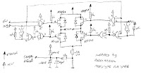
This circuit drives small DC motors up to about 100 watts or 5 amps or 40 volts, whichever comes first. Using bigger parts could make it more powerful. Using a real H-bridge IC makes sense for this size of motor, but hobbyists love to do it themselves, and I thought it was about time to show a tested H-bridge motor driver that didn't use exotic parts.

http://www.bobblick.com/techref/projects/hbridge/hbridge.html
H-bridge using P and N channel FETs
This H-bridge uses MOSFETs for one main reason - to improve the efficiency of the bridge. When BJT transistors (normal transistors) were used, they had a saturation voltage of approximately 1V across the collector emitter junction when turned on. My power supply was 10V and I was consuming 2V across the two transistor required to control the direction of the motor. 20% of my power was eaten up by the transistors. I tried darlingtons etc... nothing worked. The transistors also would get quite hot - no room for heatsinks.

http://www.armory.com/~rstevew/Public/Motors/H-Bridges/Blanchard/h-bridge.htm
N-Channel H-bridge Motor Drive
In low voltage motor drives, it is common practice to use
complementary MOSFET half-bridges to simplify the gate
drive design. However, the P-channel FET within the
half-bridge usually has a higher on resistance or is larger
and more expensive than the N-channel FET. The alternative
solution is to design in an N-channel half-bridge.

http://www.eetkorea.com/ARTICLES/2004MAY/2004MAY18_BD_MSD_PD_AN.PDF
Comparator Controlled H-Bridge Circuits (LM311)
The next two circuits are simple Bi-Polar H-Bridge circuits. The bridges are controlled by a pair of LM311 voltage Comparators.
The LM311 Voltage Comparator has several unique features, one of which is an output transistor with an open emitter as well as the typical open collector. This allows the output transistor of the comparator to sit between the bases of the power transistors.

http://home.cogeco.ca/~rpaisley4/HBridge.html
Robot Motor control
In order to control the speed/torque of a motor, a so called H-bridge can be used. I built/designed one myself, using 4 MOSFETs.

http://www.iwhat.nl/rienatmarobi/bots/Wheeley/motor/index.html
Bidirectional operation (H-bridge circuit)
We have achieved speed control and have made a powerful drive circuit. However in robotic work we also usually want to be able to drive a motor either clockwise or counterclockwise. Before we discuss the use of transistors to solve this problem

http://www.mech.uwa.edu.au/NWS/How_to_do_stuff/micro_crash_course/pwm/


