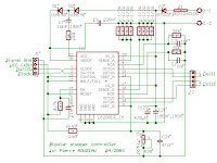
This project presents a circuit for driving high-power unipolar stepper motors. Here you will find all the information needed to make your own. This circuit allows step-level control and can be easily modified for other modes of operation
Circuit Schematic and Photo
The L297 has several inputs that can be generated by a PC/104 stack or other controller. This circuit allows you to control each step, in full-step mode. Meaning: You can tell it to move one step in either direction (of course you can make it move fast and it will continuously rotate). The two inputs are a direction and a pulse. In the next section you will find a program to control this using xPC.

http://hades.mech.northwestern.edu/wiki/index.php/Unipolar_Stepper_Motor_Driver_Circuit
Stepper motor driver circuit
Stepper Motor Data
Stepper Motor Data 1
Stepper Motor Data 2
Stepper Motor Data 3
Microstepping Data
Stepper Motor Driver Circuit
2A Step Motor Driver Circuit
bipolar stepper motor with current control
Microstep Stepper motor driver circuit
Precision Microstepping Driver Circuit
High Current Microstep Stepper Motor Driver
http://basicelectronic.blogspot.com/2009/02/stepper-motor-driver-circuit.html
Stepper motor control board
This project is actually an educational kit. One can study the full operation of unipolar type stepper motor using this board. As it is micro controller based it can be programmable also and one can learn micro controller interfacing with LEDs, key board and stepper motor. Thus single board serves the purpose of learning stepper motor control as well as learning micro controller programming.
In the construction of unipolar stepper motor there are four coils. One end of each coil is tide together and it gives common terminal which is always connected with positive terminal of supply. The other ends of each coil are given for interface. Specific color code may also be given. Like in my motor orange is first coil (L1), brown is second (L2), yellow is third (L3), black is fourth (L4) and red for common terminal.

http://electrofriends.com/microcontrollers/stepper-motor-control-board/
Stepper motor controller
The stepper motor driver circuit shown as following

The opto-isolator are important which prevent destroy of MCU by the feeback voltage from
power transistor. Two adjust-able voltage regulator used to adjust the running voltage and
stopping/holding voltage of the stepper motor.
http://www.geocities.com/mindtan2000/PIC.html
Remote Unipolar Stepper Motor Controller with 89C51
Abstract:- This is the third and most amazing application of multichannel IR remote where 4 different channels of remote are utilized to control all the parameters of unipolar stepper motor. All three parameters of stepper motor RPM, direction & no. of revolutions can be changed from remote. 89C51 takes care of all the controlling actions.
The project is based on stepper motor control and I have experimented with unipolar stepper motor. One must know first how this stepper motor is controlled. How it can be rotated, how RPM, direction & no. of revolutions can be changed etc. So let us first go through the theory of unipolar stepper motor

http://www.jasonbabcock.com/computing/breadboard/bipolar/index.html
Controlling Stepper Motor with a Parallel Port
This is an easy to build stepper motor driver that will allow you to precisely control a unipolar stepper motor through your computer's parallel port. With a stepper motor you can build a lot of interesting gadgets such as robots, elevator, PCB drilling mill, camera panning system, automatic fish feeder, etc. If you have never worked with stepper motors before you will surely have a lot of fun with this project.

http://electronics-diy.com/stepper_motors.php
Stepper Motor Controller
he stepper motors were purchased at a local auction house. They took apart old hard drives and printers and such selling the parts separately. You can usually barter and get a good deal, the ones being used in this circuit cost about $3 each. These particular motors are unipolar steppers. You can usually tell by the number of wires coming out. This one has 6 wires coming out of it: 2 green, 1 blue, 1 yellow, 1 red, and 1 white. In a 4 phase unipolar motor There are 2 coils which are center tapped and have a wire for each of phases. If the wire colours are random or if there were only 5 wires, then you would have to use an ohmmeter to distinguish between the phases and center tap. Fortunately for me 2 of the wires were the same colour, so they must be the center taps. Another plus was the wires were grouped in threes.

http://homepage.usask.ca/~avl094/Electronics/Stepper/
Stepper power board based upon L6208 circuit
Find herebelow my own design for stepper command board based upon L6208 circuit.
Stepper bipolar command (4 wires)
Maximum current 2.5A per phase
Mode : 1/2 step
Bridge control : 'Slow decay' (see datasheets)
Command Step/direction
Power supply unstabilised, but rectified and filtered, maximum 32V
Power supply stabilised, maximum 40V.
Forced blow on circuit required.
Board presented here is slightly different from prototype, i've locked it in half-step and control mode in 'Slow decay'. I've improve design and distance between wires.
This board don't have been tested at maximum current (only tested at 2A), nor in intensive service.
While integrated circuit accept a maximum current of 2.8A, i've limited the board to 2.5A.
I've tested without cooling, heating is intense (~100°C), and circuit disjunct over 1.8A. With a small blower, temperature remains very reasonnable

http://www.otocoup.com/CarteL6208_e.htm#Specif


