Showing posts with label sensor. Show all posts

Thursday, April 16, 2009

Infrared motion detector with Microcontroller Circuit


A simple automatic motion-detection Digital Camera Circuit

When the sensor detects movement in a room it will take a burst of
10 photos with the digital camera. Each photo is taken at 0.5sec
interval. After the 10 photos, the camera waits 3 seconds for further
movement and if it is detected, the process is repeated until 80
photos are taken.
The photos can then be downloaded to your PC (via the USB
connection on the board) for viewing.


more

The Directional Infrared Detector Module Circuit (DIRM)

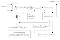
Figure shows a block diagram of the DIRM. A Fresnel lens
captures the incident IR and focuses it towards the
pyroelectric sensor increasing the sensitivity of the sensor
and improving its directional response. The resultant signal
passes through a low pass filter, which removes any high
frequency noise generated by mechanical vibration. The
output of the filter is then fed into a differentiator, which
produces an output voltage proportional to the rate of
change of the incident IR. The frequency response of this
differentiator is also rolled off at high frequencies, further
reducing the effects of undesired signals. The window
comparator produces a logic output whenever the rate of
change of incident IR exceeds a given set point.
An 8-bit PIC16F84 microcontroller processes the logic
signals and controls the rotating platform and reports
information to the team leader.

more


PIR DETECTOR USING ST7FLITE05 MICROCONTROLLER
A PIR detector can be made easily with ST7FLITE05 using the
circuit shown in Figure. The sensor interfacing circuit (shown on
the left side of the microcontroller in Figure ) can be divided
into the following modules:
1.Transistor circuit used as an amplifier.
2.Transistor biasing controlled through the microcontroller.
3. Software-controlled transistor output.


more pdf


Infrared, Alarm, and PIC Microcontroller
OBJECTIVES:
• Get familiar with an infrared emitter diode and receiver.
• Create an obstacle detector with an infrared emitter and receiver.
• Learn about PIC microcontroller and programming a PIC microcontroller.
• Write a PIC program and build the circuit of a household alarm system.


more pdf


Ultra-low Power Motion Detection using the MSP430F2013

A system capable of detecting motion using a dual element PIR
sensor is shown in Figure 1 using the MSP430F2013
microcontroller. Using the integrated 16-bit Sigma-Delta
analog-todigital converter and built-in front-end PGA (SD16_A),
the MSP430F2013 provides all the required elements for interfacing
to the PIR sensor in a small footprint. With integrated analog
and a 16MHz, 16-bit RISC CPU, the MSP430F2013 offer a great
deal of processing performance in a small package and at a low cost.

Wednesday, April 15, 2009

PIR Infrared motion detector Circuit

Infrared motion detector Circuit
The pyroelectric sensor is made of a crystalline material that
generates a surface electric charge when exposed to heat in the
form of infrared radiation. When the amount of radiation striking
the crystal changes, the amount of charge also changes and
can then be measured with a sensitive FET device built into the
sensor. The sensor elements are sensitive to radiation over a wide
range so a filter window is added to the TO5 package to limit
detectable radiation to the 8 to 14mm range which is most sensitive
to human body radiation.
Typically, the FET source terminal pin 2 connects through a
pulldown resistor of about 100 K to ground and feeds into a two
stage amplifier having signal conditioning circuits. The amplifier
is typically bandwidth limited to below 10Hz to reject high
frequency noise and is followed by a window comparator that
responds to both the positive and negative transitions of the
sensor output signal. A well filtered power source of from 3 to
15 volts should be connected to the FET drain terminal pin 1


more


MX063 PIR SENSOR LIGHT Circuit


more


Application Schematic of Pyroelectric Infrared Motion
Sensors Circuit
Note: For best results the power supply should be very stable
at a constant +5V DC +/- .2V.This Schematic is offered for reference only without warranty
of any kind. Microsystem Technologies does not support user
designs or implementations that use this circuit


more


Automatic security lights Circuit
Combination PIR sensor and floodlight units are cheap but
rather inflexible if you want to locate the sensor and light in
different places. In my case, I wanted to detect movement
on the driveway and switch on the lights in the carport around
the corner. Yet another job for the ubiquitous PICAXE-08
microcontroller


A standard PIR sensor is used as the movement detector.
The sensor interfaces to the PICAXE (IC1) on input 2 (pin 5).
This pin is pulled low via isolation diode D3 and the normally
open (NO) output of the sensor whenever movement is
detected. It can also be pulled low by transistor Q1, which acts
as a simple inverter for sensors with normally closed (NC) outputs.
more


Passive Infrared Motion Detector Circuit

This circuit was originally reverse -engineered from a motion
detecting yard light that I ripped apart. That's still probably the
best way to get the parts at a reasonable price, especially the
pyroelectric sensor and the absolutely necessary Fresnel lens.
The signal at pin 7 of the 324 is very interesting and fooling with
the filtering around the first amplification stage can make it even
more so. The LM324 is a wonderful little bug, and you will find
many uses for the window comparator if you look at it the same
way you would learn a new really useful knot. It all works on a
single 5 volt supply. The sensor is only sensitive to changes
across its surface, so don't expect a signal from a static object
even if it is hot. Yard lights are turning up at flea markets and yard
sales as people find themselves heads up every time the cat walks
past. This circuit is in a machine that sees people moving 40 feet
away.


Wednesday, April 8, 2009

4-20mA Pressure Transducer Circuit


Complete 4-20mA Pressure Transducer Solution with
PGA309 and XTR117

The XTR117 is a precision current output converter designed
to transmit analog 4-20mA signals over an industry-standard
current loop. It provides accurate current scaling and output
current limit functions.

XTR117 datasheet pdf

The PGA309 is a programmable analog signal conditioner
designed for bridge sensors. The analog signal path amplifies
the sensor signal and provides digital calibration for
zero, span, zero drift, span drift, and sensor linearization
errors with applied stress (pressure, strain, etc.). The calibration
is done via a One-Wire digital serial interface or
through a Two-Wire industry-standard connection. The
calibration parameters are stored in external nonvolatile
memory (typically SOT23-5) to eliminate manual trimming
and achieve long-term stability.

PGA309 datasheet pdf

Tuesday, March 24, 2009

Rotary Encoder Circuit

Rotary Encoder
A digital optical encoder is a device that converts motion into
a sequence of digital pulses. By counting a single bit or by
decoding a set of bits, the pulses can be converted to
relative or absolute position measurements. Encoders have
both linear and rotary configurations, but the most common
type is rotary. Rotary encoders are manufactured in two
basic forms: 1) the absolute encoder where a unique digital
word corresponds to each rotational position of the
shaft, and 2) the incremental encoder, which produces
digital pulses as the shaft rotates, allowing measurement of
relative position of shaft. Most rotary encoders are
composed of a glass or plastic slotted disk. As radial
lines in each track interrupt the beam between a photoemitter-
detector pair (or Optointerrupter), digital pulses are produced.


Inexpensive rotary encoder
The circuit outputs are high as default. When the spindle
is turned, there will be pulses on the outputs. The lower
square wave output signal leads or lags 90 degrees in
respect to the upper signal - it depends on the direction
the spindle is turned. The circuit works from 2V up to 36V,
so 3.3V logic works too. The LM393 gives out good pulses
with as little as 5mV differential input, which means that this
circuit works even when the motor is turned very slowly.


Rotary encoder converter circuit
This circuit used convert signal from Rotary encoder (A,B) to
two pulse signal
- Y for CCW direction
- X for CW (clockwise) direction
Two pulse signal is easy for microcontroller programing
The circuit used two D-type flip-flop(74HC74D) for the judgement.


Magnetic Rotary Encoder Design
Inspired by Nopheads fantastic printing progress using his
encoder, I decided that RepRap would greatly benefit by having
an awesome, standardized rotary encoder board. The optical
encoders can be finicky and hard to mount. Many RepRappers
have also had great success in the past using AS50**
family chips, so I decided to go that route.


Rotary Encoder Counter Circuit
If we re-design the encoder to have two sets of LED/phototransistor
pairs, those pairs aligned such that their square-wave output signals
are 90o out of phase with each other, we have what is known as a
quadrature output encoder (the word "quadrature" simply refers to
a 90o angular separation). A phase detection circuit may be made
from a D-type flip-flop, to distinguish a clockwise pulse sequence
from a counter-clockwise pulse sequence:


Quadratrack: Using Mechanical Rotary Encoders
These mechanical encoders generate a "quadrature" signal. I
don't know the origin of the term quadrature but basically it
means there are four states that this device can be in. Further,
transition from one state to the next is well defined so with a
simple circuit or some software you can translate the pulses
into rotation movement.

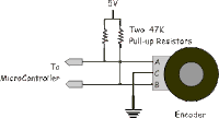
The three pins on the device are A, B, and Common.
Since they are mechanical they are simply switches that
connect the A pin, the B pin, and then both the A and B
pin to the C pin. A simple circuit for hooking this up is shown
below